Nearfield Optics
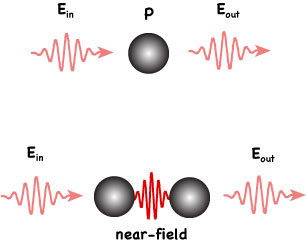
In conventional optical imaging and spectroscopy, an object is typically irradiated by a light source and the scattered or emitted light is recorded by a detector. That situation, illustrated on the top of the figure on the left, constitutes the canonical optics problem: The incident field Ein induces in the object polarization currents, which in turn give rise to an emitted field Eout In the canonical near-field optics problem, on the other hand, the object is split into two parts, as shown on the bottom of the figure on the left. One part is referred to as the probe and the other part as the sample. Typically, the probe is engineered to exploit the unique properties of metal nanostructures at optical frequencies to localize incident radiation and enhance the light-matter interaction on the sample. For example, when a light wave is incident on a tiny gold probe the incident field periodically displaces the probes electrons with respect to the lattice. Near resonance, that charge oscillation gives rise to a greatly amplified electric field just outside the probe, which then affects the nearby sample.
The field Eout emitted by the combined system is detected and serves as a source of information from which the sample properties are reconstructed. Manipulating the relative separation between probe and sample adds to the information content. A near-field image is recorded by raster scanning the probe over the sample, or vice versa, while continuously detecting the emitted field. Typically, an image is represented as a two- dimensional scan f[Eout(x, y)], where f stands for a function of the field, such as intensity or an interferometric signal. The enhanced resolution, which can be as fine as 10 nm if visible or IR light is used, originates from the conversion of nonpropagating field components confined on the sample surface to propagating radiation in the presence of the probe.
A near-field can arise from primary sources, such as electrically driven currents, or secondary sources, such as induced polarization currents. The choice of basis in which to express the field depends on the geometry of that source. For example, the fields near a planar sample surface are conveniently expanded in a plane-wave basis, also known as the angular spectrum representation, and can be described as a superposition of propagating plane waves and evanescent waves, whose field amplitudes decay exponentially from the surface. The localized evanescent waves are also the source of the fields’ high spatial frequencies.
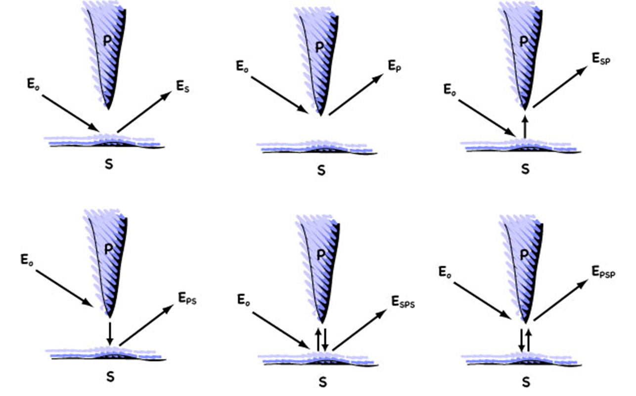
A near-field measurement captures the field Eout generated by the currents, primary or secondary, that define the probe-sample system. These currents result from the interaction between probe and sample and do not reflect the properties of the sample alone. To understand the mutual interaction of probe and sample, one can think of the near-field interaction in terms of a perturbation series, similar to a Born series in standard scattering problems. As illustrated in the figure above, the field Eout can then be written as a sum of discrete interactions
E = ES + EP + ESP + EPS + EPSP + ESPS + .. . (1)
where ES and EP are the fields emitted (or scattered) from the sample and probe, respectively; EPS is the field scattered by the sample and then emitted by the probe; ESP, in turn, describes the reverse - the field scattered by the probe and emitted by the sample.
Additional interactions contribute as higher-order terms in the series.
Fortunately, near-field microscopy exploits prior knowledge of probe and sample properties, which makes it possible to greatly suppress most terms in the series. For example, the signal measured by photon scanning tunneling microscopy (PSTM), in which photons - or more accurately, evanescent waves confined to a surface -“tunnel” from the sample to the probe, is dominated by the term ESP. In contrast, the signal measured by illuminationmode aperture-probe microscopy, in which the sample is excited by the field from a small hole at the probe’s tip, is dominated by the EPS term.
Individual interactions at sample and probe may involve different frequencies. Tip-enhanced Raman scattering (TERS), which relies on laser light to excite the vibrational modes of surface molecules on the sample, involves EPSP, but with input and output frequencies that differ by an amount corresponding to the energy of vibrational modes. Depending on the signal to be measured - whether from Rayleigh scattering, fluorescence, Raman scattering, or some nonlinear response of a system - one has to account for the coherent or incoherent sum of interaction orders. It is convenient to divide different interaction schemes into two subgroups - a “strong probe” group, which comprises EPS , EPSP, and their related higher orders, and a “weak probe” group, which comprises ESP , ESPS, and so forth. In the strong probe regime, as the name implies, incident radiation interacts more strongly with the probe than with the sample; the opposite is true in the weak probe regime. Although qualitative, the classification scheme helps researchers interpret experimental near-field data.
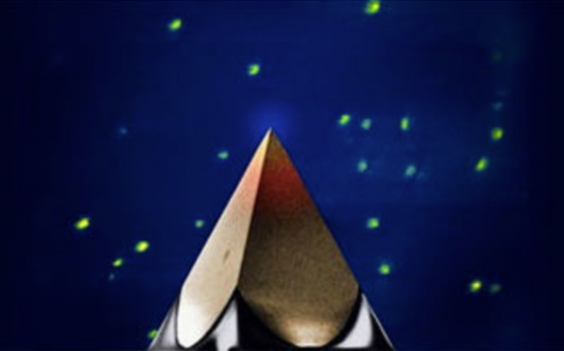
The figure on the left shows a fluorescence image of single nile blue molecules dispersed on a glass surface. The molecules are locally excited by the enhanced fields of a gold pyramid probe (inset). The probe is raster-scanned over the sample surface and the fluorescence emitted by the molecules is collected pixel-by-pixel through a distant lens.
Related publications:
[1] L. Novotny, ”The history of near-field optics,” Progress in Optics 50, 137-180, E. Wolf (ed.), Elsevier, Amsterdam (2007).
[2] T. W. Johnson, Z. J. Lapin, R. Beams, N. C. Lindquist, S. Rodrigo, L. Novotny and S.-H. Oh, ”Templated mass production of ultra-sharp metallic probes for near-field optical microscopy,” ACS Nano 6, 9168-9174 (2012).
[3] L. Novotny, ”From near-field optics to optical antennas,” Physics Today, 47-52 (July 2011).
[4] L. Novotny and S. J. Stranick, “near-field optical microscopy and spectroscopy with pointed probes,” Ann. Rev. Phys. Chem. 57, 303-331 (2006).
[5] C. Höppener and L. Novotny, ”Antenna-based optical imaging of single Ca2+ transmembrane proteins in liquids,” Nano Lett. 8, 642-646 (2008).